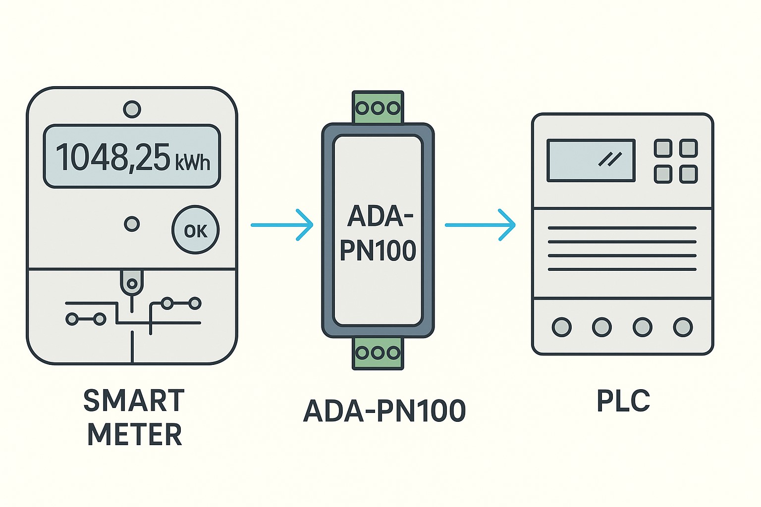
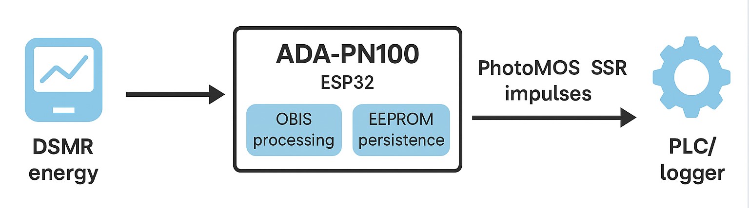
Az ADA-PN100 egy ESP32-alapú, okosmérők P1 portjáról olvasott OBIS adatokból
S0 (számlálható) impulzusokat előállító eszköz. Célja, hogy a modern
okosmérőkből kinyert energiaértékekből kompatibilis, impulzusjeleket adjon
PLC-knek, mérőrendszereknek, adatgyűjtőknek vagy SCADA-knak.
Röviden: P1 OBIS → feldolgozás → konfigurálható idejű (ms) és
mennyiségű (Wh/impulzus) S0-szerű impulzusok egy leválasztott,
potenciálfüggetlen PhotoMOS kimeneten (GAQY212GS).
Mire jó?
Régi S0 számlálók/PLC bemenetek meghajtása okosmérős adatokból.
Fogyasztás/termelés impulzus-kimenet (kWh alapú), kompatibilis ipari 24 VDC digitális bemenetekkel.
PV-export/-import szétválasztott impulzus külön OBIS kódokkal (pl. vételezett: 1-0:1.8.0, betáplált: 2-0:2.8.0).
Egyszerű integráció adatgyűjtőkhöz, loggerekhez, BMS/EMS/SCADA rendszerekhez, ha impulzust várnak.
Fő jellemzők
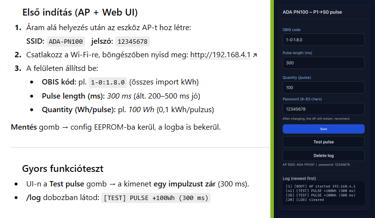
OBIS alapú feldolgozás: 1-0:1.8.0 (alapértelmezett, kWh), egyéb OBIS is megadható.
Konfigurálható impulzus hossza: 50–2000 ms (alap: 300 ms).
Konfigurálható Wh/impulzus (pl. 100 Wh → 0,1 kWh/impulzus).
Feszültségküszöb események számlálása (egyedi logika esetén)
Az ADA-PN100 firmware alapvetően kWh-alapú impulzust ad, de tetszőleges OBIS olvasható.
Ha nem kWh jellegű kódot adsz meg (pl. kW), akkor a mennyiségi helyesbítéshez
(Wh/impulzus) célszerű az integrálás logikáját a firmware-ben bővíteni (projektfüggő).
Impulzus sűrűség megválasztása
A Wh/impulzus érték határozza meg, milyen sűrűn érkeznek az impulzusok. Példa:
AP jelszó módosítás (opcionális): a mentés után az AP újraindul, csatlakozz az új jelszóval.
Próba: Test pulse gomb → PLC számláló növekedését ellenőrizd.
Hibaelhárítás
Nincs impulzus:Test pulse működik? Ha igen, a P1/OBIS feldolgozás lehet a gond (nem nő a kWh).
Ellenőrizd az OBIS kódot és hogy valóban változik-e.
A PLC nem számol: bemeneti típus megfelelő? 24 VDC DI vagy S0 számláló kell.
Minimális impulzushossz legyen 30–50 ms felett.
Szórványos téves impulzus: nagyon nagy impedanciájú bemenetnél ritkán érzékeny lehet a PhotoMOS
szivárgásra. Tegyél gyenge lehúzót (pl. 10–47 kΩ) a bemenet és 0V közé.
AP-hoz nem tudsz csatlakozni: tartsd nyomva a RESET gombot ≥5 s és indulj újra gyári jelszóval.
Biztonság és korlátok
Max. 60 VAC/DC kimeneti feszültség! 230 VAC hálózatot ne kapcsolj.
Az impulzus kimenet leválasztott PhotoMOS, potenciálfüggetlen, de ipari környezetben a
zajok miatt figyelj a kábelezésre (árnyékolt vagy rövid vezeték, közös referencia a PLC-vel ha szükséges).
A P1 porthoz a firmware invertált DSMR, 115200 8N1 beállítást használ.
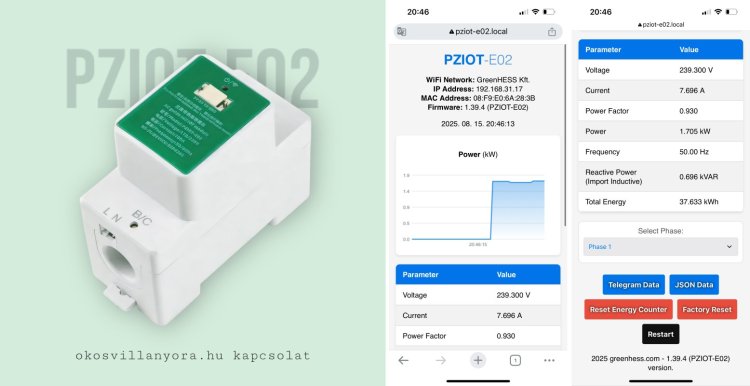
A fázismérés svájci bicskája
A PZIOT-E02 kétféle helyzetben adhat hatalmas segítséget:
1. Ha nincs P1 portos villanyórád
Ilyenkor a PZIOT-E02 önálló fázismérőként működik.
Egy fázison képes mérn…
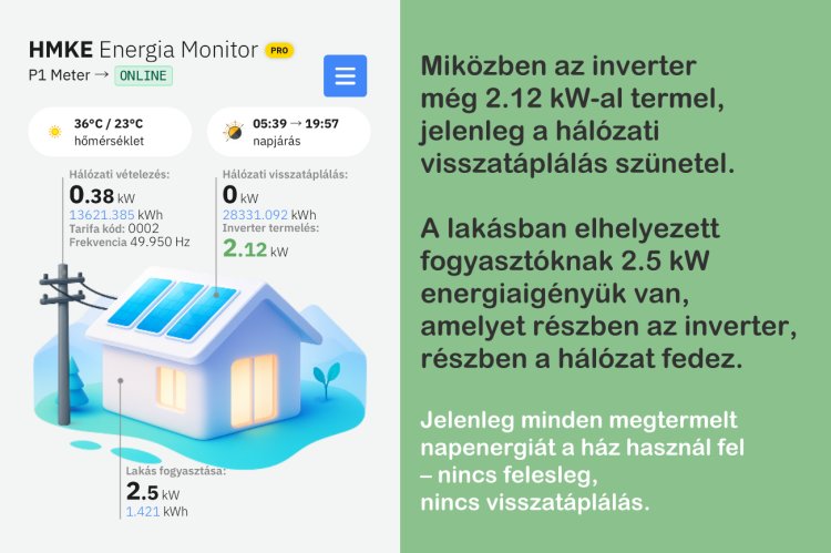
A háztartási méretű kiserőművek (HMKE) tulajdonosai számára
természetes, hogy figyelik a hálózatba történő visszatáplálást. Ez az
érték mutatja meg, mennyi megtermelt energiát nem használ fel a há…
Az elmúlt időszakban egyre több magyar háztartásban vált fontossá, hogy ne csak a villanyszámlát lássák, hanem azt is, mi történik valójában a háttérben. Erre ad választ a debreceni fejlesztésű ADA P1…